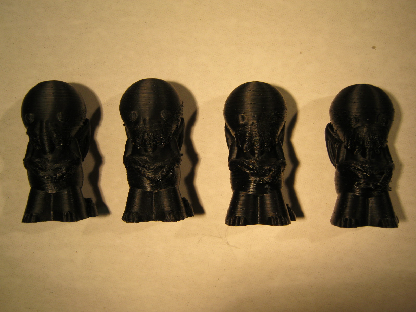
One thing I’ve noticed in some of my prints is the tendency to “drool” a bit on the edges, sort of like a hernia. This is caused by the extruded plastic layer still being soft when the next layer is put on top of it, causing the bottom layer to bulge out a bit (or even a lot). This will typically be seen when the perimeter of the piece is small (makes sense, right?). The obvious solution is to give the layer time to solidify, and easiest way is to simply slow down the speed of the head. I recently ran a small experiment to test the effect of slower speeds.
For my test piece I chose something from Thingiverse called “cthulhu2”. It’s not too big, so it’s not overly expensive in terms of time to print … that is, I can do it in the evening after work.
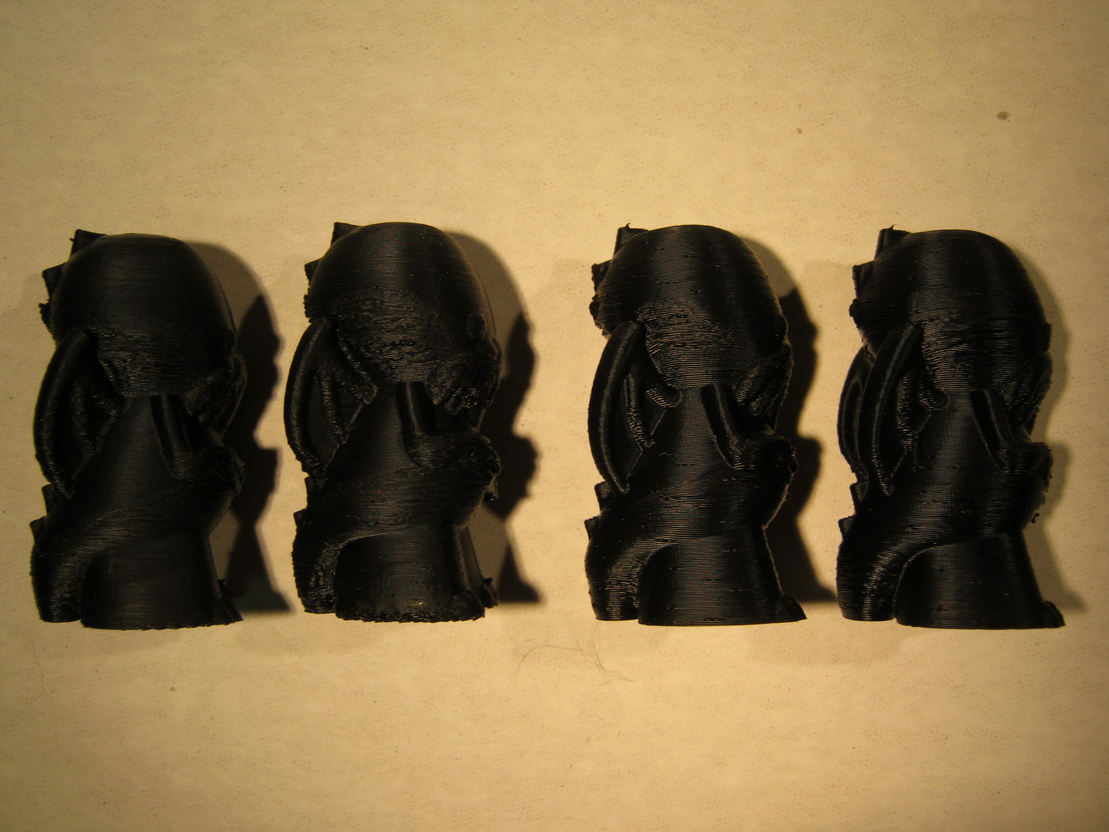
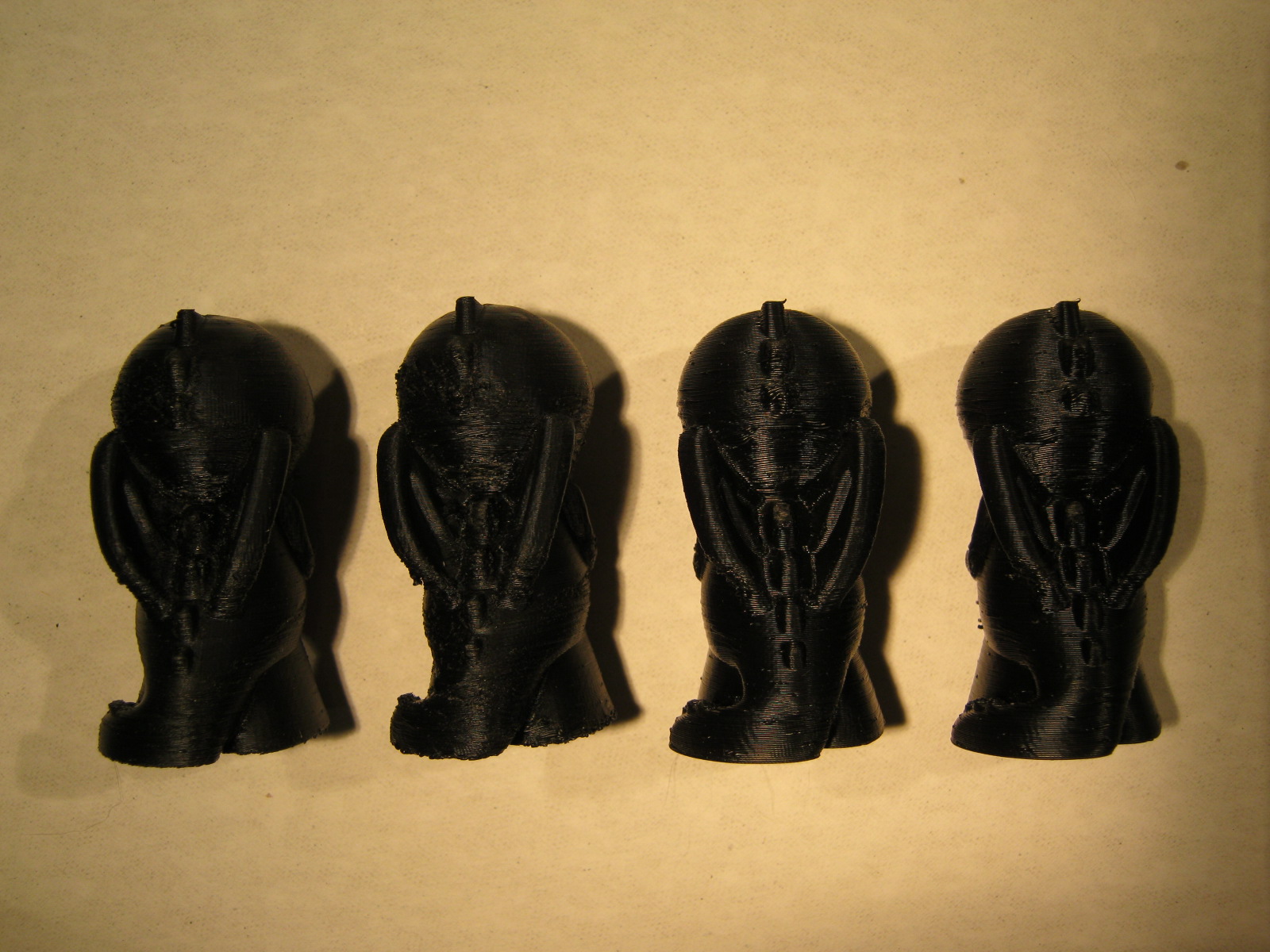
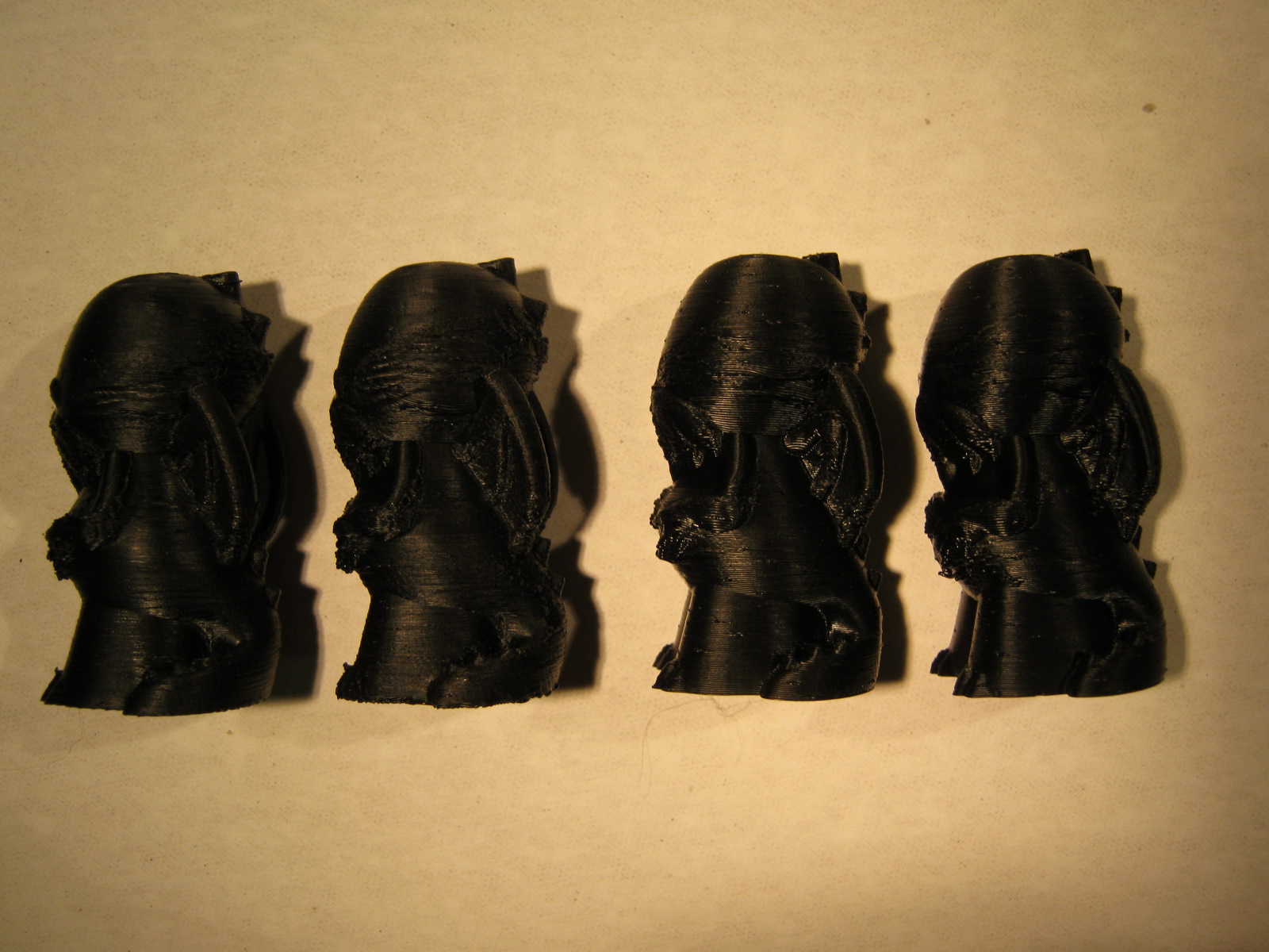
The normal speed that I use is 60 mm/second (recommended by the manufacturer). For testing, I tried 30 mm/second. Overall, this seemed to help, but wasn’t a complete cure. I also tried printing at both 0.1 and 0.2 mm/layer. The following pictures show the results. If the pieces are numbered 1 through 4, left through right :
piece layer speed infill time-t0-print
(mm) (mm/sec) (minutes)
1 0.1 30 1.5 162
2 0.1 60 3 192
3 0.2 60 3 75
4 0.2 30 1.5 85
Reducing the amount of infill certainly improves the speed, but there’s always a danger of droops at the top or at overhangs. There’s no evidence of droop at the tops here, but #4 does show a bit of a problem on the tummy, just below the hands.
You can certainly see the effect of printing at 0.1 and 0.2 mm/layer, both on the quality of the print and the length of time it takes to complete the print.
I list the SLIC3R parameters after the pictures.
Here are some pictures of the pieces. Keep in mind that these correspond with the piece#, from left to right. You’ll want to zoom in to see all the types of issues, and how it changes from piece to piece.
The STL files were sliced with the SLIC3R program. Here’s a sample printer ini file :
# generated by Slic3r 0.9.1 on Sun Sep 30 13:36:08 2012
bridge_flow_ratio = 1
bridge_speed = 60
brim_width = 0
complete_objects = 0
external_perimeter_speed = 100%
extra_perimeters = 1
extruder_clearance_height = 20
extruder_clearance_radius = 20
extrusion_width = 0
fill_angle = 45
fill_density = .15
fill_pattern = honeycomb
first_layer_extrusion_width = 200%
first_layer_height = 100%
first_layer_speed = 70%
gcode_comments = 0
infill_every_layers = 1
infill_extruder = 1
infill_extrusion_width = 0
infill_speed = 60
layer_height = 0.2
notes =
output_filename_format = [input_filename_base].gcode
perimeter_extruder = 1
perimeter_extrusion_width = 0
perimeter_speed = 30
perimeters = 3
post_process =
randomize_start = 1
skirt_distance = 8
skirt_height = 1
skirts = 2
small_perimeter_speed = 30
solid_fill_pattern = rectilinear
solid_infill_speed = 60
solid_layers = 3
support_material = 0
support_material_angle = 0
support_material_extruder = 1
support_material_extrusion_width = 0
support_material_pattern = rectilinear
support_material_spacing = 1
support_material_threshold = 45
threads = 2
top_solid_infill_speed = 60
travel_speed = 160


